
Dusk To Dawn Wiring Diagram
OVERVIEW Leviton Photocells monitor ambient light levels and provide a DC analog signal to various microprocessors and energy management systems for the purpose of lighting control. There are 4 different styles with 4 different possible ranges for a total of 16 basic varieties. Styles Include: Indoor, Outdoor, Atrium and Skylight
Photocell Wiring Diagram Pdf Wiring Diagram
and wiring diagrams . PHOTO CONTROLS Fixed Position Mounting Watts Tungsten VA Ballast AMPS Tungsten AMPS Ballast 'Not UL or CSA Certified Stem Mounting Watts Tungsten. Shop for Intermatic K4221C thermal type photocell. Great prices and fast shipping on Intermatic thermal type photocells at 1000Bulbs.com! Keywords: intermatic k4221c, photo.

Diagram Of A Photocell
OPERATION. The Power Pack relay can be turned ON and OFF automatically using an occupancy sensor input, photocell input (-RD3 and -RD4 models), or manually from an optional low voltage switch (-0D2 and -RD4 models). The OPP20 power pack will always power up with the latching relay in the closed (ON) state; 5s after power on the inputs.

Lowenergie Photocell Wiring Diagram yazminahmed
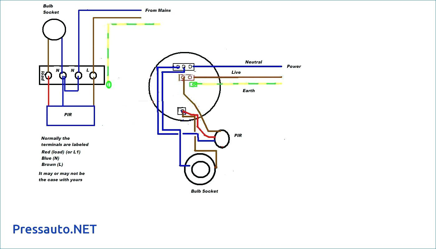
INSTRUCTIONS 240v External Photocell Box (LRPC240-BX) WARNINGS PLEASE READ THESE INSTRUCTIONS CAREFULLY PRIOR TO INSTALLATION OR USE. WIRING DIAGRAM: PHOTOCELL CABLES Output Cable Neutral (N) - Blue Live Out (X) - Red Live In (L) - Brown Photocell N X L Fitting Mains Input Cable *Colour of wire sleeving may vary from mains supply
Photocell Wiring Diagram Pdf Search Best 4K Wallpapers
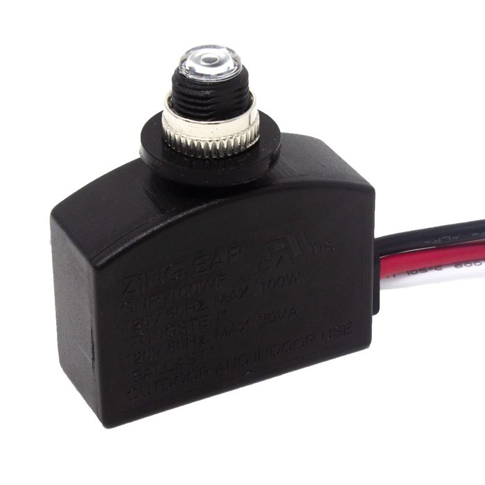
1. Load line (Lo) 2. Neutral line (N) 3. Supply or live line (LI) In most photocells, the load line wire is RED, the neutral wire is WHITE and the Supply line is black. This colour code is not universal. It may change depending on the manufacturer of the photocell switch. The picture of the terminals of a brand of photocell is shown below:

Photocell Wiring Diagram Easy Wiring My XXX Hot Girl
What is a photocell? Photocells are sensors that allow you to detect light. They are small, inexpensive, low-power, easy to use and don't wear out. For that reason they often appear in toys, gadgets and appliances. They are are often referred to a CdS cells (they are made of Cadmium-Sulfide), light-dependent resistors (LDR), and photoresistors.

Wiring Diagram For Photocell Lights Wiring Boards
Manual for CAME DIR / R-Series Photocells. Includes DIR10, DIR20, DIR30, 001DIR10, 001DIR20, 001DIR30
Photocell Wiring Diagram Pdf Wiring Diagram Image
Install photocell and wire as per diagram. 2. Use photocell rated for your supply voltage. TROUBLESHOOTING 1. Check that the line voltage at the fixture is correct.. For 0-10V dimming version, please check wiring diagram below. 12 tapped holes surface conduit or photo control) 12 ps Tapped oles 5/1 dia. crew hole Front housin crew ealin rin.

Photocell Wiring Diagram Pdf
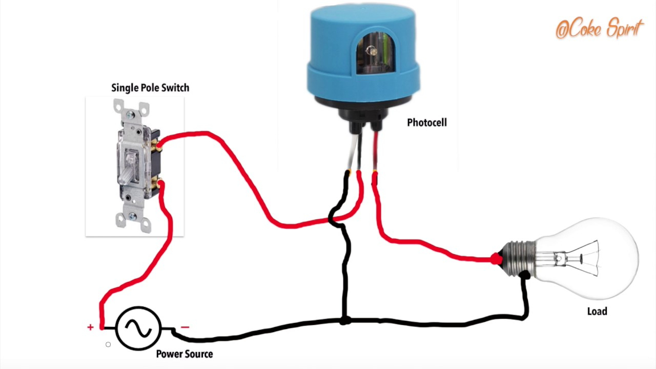
Short version how, what and where to do with the three wires on that photocell you want to use to automatically turn your lights on at dusk and off at dawn..
120V Wiring Diagram Wiring Diagrams Hubs Photocell Wiring Diagram Pdf Wiring Diagram
A diagram that shows how to wire a photocell (a photoresistor or light sensor) into an electrical circuit is known as a photocell wiring diagram. This is used to regulate lights based on light levels in the environment. A 208V photocell wiring diagram is drawn by connecting a photocell to control lighting in a circuit that operates at 208 volts.
Photocell Wiring Diagram Artsied
Photocell Circuit Diagram The photocell used in the circuit is named as dark sensing circuit otherwise transistor switched circuit. The required components to build the circuit mainly include breadboard, jumper wires, battery-9V, transistor 2N222A, photocell, resistors-22 kilo-ohm, 47 ohms, and LED.

Photocell Wiring Diagram Pdf Wiring Diagram
Photocell Instructions Page 1 For models: PC10A & PC10AH This installation must be carried out by an electrician. Please read these instructions carefully before installation. Leave a copy for the user/maintenance engineer for future reference. Specification Photocell kit & Photocell Head Class II construction and must not be earthed.
29 Photocell Wiring Diagram Pdf Wiring Diagram List Wiring Diagram
A wiring diagram for a photocell consists of two main parts: a schematic diagram and a wiring diagram. The schematic diagram shows the components of the photocell system, including the photocell itself, the fixtures, and the wiring. The wiring diagram shows how the components are connected.

12 Volt Photocell Wiring Diagram Coearth
A photocell wiring diagram is typically composed of several elements. First, the circuit diagram will show the power source, the photocell, and the various components the photocell needs to be connected to. It will also show the connections for both the photocell and the components.

How To Wire A Photocell To Multiple Lights
Here is my wiring diagram ( third photo) and instructions: CAUTION: BLACK WIRE IS 120 VOLTS, SO TURN OFF SWITCH OR CIRCUIT BREAKER. Connect sensor's black wire to black wire coming from house. Connect red sensor wire to light's black wire . Connect all 3 white wires (from house, from sensor and from light) together. Now wasn't that easy. :-)
Wiring A Photo Cell. (Dusk To Dawn) Youtube Photocell Wiring Diagram Pdf Wiring Diagram
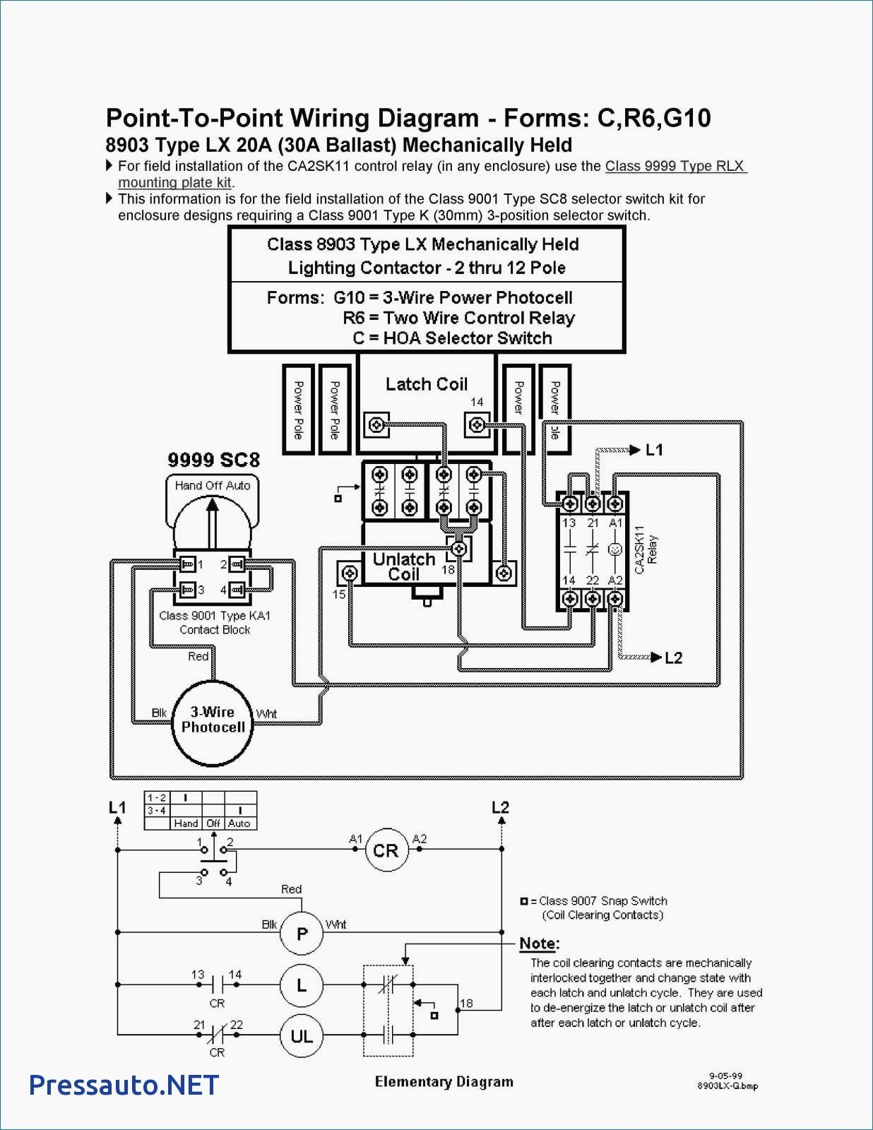
The schematic wiring diagram below shows how to wire a photocell switch with a 3-phase contactor to power nine (9), 250W lighting loads: Note that on the photocell sensor, L1 is the live wire, N is the neutral wire and Lo, is the load wire which goes to energize the contactor coil which must be rated for the phase voltage ( L1-N or L2-N or L3 -N ).